Mining operations contain many serious hazards. This guide addresses only one specific category of them.
Mining sites involve blasting, dust, noise, electrical systems, ground movement, heat, vehicle proximity and dozens of other hazard categories. This guide does not address any of them.
What this guide does address is a specific and recurring pattern: the moment when a worker's hand becomes the primary interface between a person and a load, component, tool or struck surface — because no engineered alternative exists or has been provided.
Where the PSC/HSF product range does not have a credible intervention, this guide says so. Including a mining hazard in this book does not guarantee that we have an appropriate solution for it. The final chapter of the applications section makes this explicit.
PSC Hand Safety India Pvt. Ltd. engineers, manufactures and distributes a range of hand-exposure elimination tools for industrial applications globally. Founded in Visakhapatnam, India, PSC has over two decades of experience in industrial safety supply and specialised equipment for the mining, steel, oil & gas, and construction sectors.
PSC products are designed around a single engineering principle: wherever a worker's hand can be removed from a hazard zone without reducing control of the task, it should be.
Hand Safety First® is a PSC Hand Safety brand focused on the doctrine of engineered hand separation. The HSF philosophy holds that hand injuries in industrial settings are primarily an engineering problem — not a behaviour problem — and that the correct response is to design or provide an interface that makes hand contact unnecessary.
Stand-off push/pull and remote load engagement tools for suspended and moving loads.
Remote holding tools that remove the holder's hand from the strike zone.
Magnetic handling interfaces for suitable ferrous surfaces — not a lifting-rating claim.
Remote load orientation and tagline retrieval tools for crane lifts.
Engineered handling interfaces for awkward, tubular and cylindrical objects.
The engineering principle that drives every product, every application and every page of this guide.
Before any product is considered, before any solution is proposed, the correct starting point is observation. Walk the task. Watch the worker. Find the hand.
In most mining maintenance, handling and rigging tasks, the hand is present for a reason. It is providing a function. It is pushing, steadying, guiding, holding, retrieving, aligning or positioning something. That function is real and necessary. The question is not whether the hand should be doing something — it is whether the hand is the only available way to do it.
The worker reaches toward a suspended load, a landing component, a struck tool or an awkward assembly. The hand enters a zone of crush, impact or strike energy.
If the hand is providing a specific function — guiding, pushing, holding — an engineered tool may be able to provide that same function from a safer position. The hand moves. The function remains.
Many hand exposures during suspended-load work arise because the worker's hand was the only available tool for the task at that moment. There was no engineered interface to provide the guidance or control function. The hand filled the gap.
This pattern recurs across suspended-load rigging, heavy-component reinstallation, strike work, pipe handling and many other tasks throughout a mine site. Many hand exposures in mining arise not simply from behaviour, but because the worker's hand is performing a necessary task function for which no practical engineered interface has been provided.
The load swings. The worker reaches out to steady it. The hand is between a moving mass and a fixed structure. The worker has no other way to control the load's position.
The hand is the interface. The exposure is real. The injury is predictable.
A stand-off push/pull tool provides the same steadying function from a position that keeps the worker's body and hands clear of the crush zone.
The function is preserved. The hand moves away. The exposure is reduced.
This distinction matters for how we approach every application in this guide. We are not asking workers to be more careful — we are asking what tool should have been provided so that careful was no longer the only protection available.
Every hand exposure addressed in this guide can be classified by the function the hand is performing when it enters the hazard zone. There are eight. Understanding the function is the first step toward finding an engineered alternative. Note that positioning is treated as a task outcome — achieved through one or more of these functions — rather than a separate function in its own right.
The hand applies directional force to move a load or component away from the worker or toward its destination.
The hand draws a load, line or component toward the worker or toward a required position.
The hand maintains the position of an object — a chisel, a pin, a component — while force is applied from another direction.
The hand directs the path of a moving load or component. Without guidance, the object would drift, rotate or travel to an uncontrolled position.
The hand reaches toward a load, line or component to collect, re-engage or recover it — often after a lift is complete.
The hand places a component so that it mates correctly with a receiving surface, bore, flange or structure.
The hand provides the grip and force to raise a component from rest — where geometry or surface creates an exposed grip position.
The hand prevents unwanted movement or rotation of a load or component that is otherwise prone to shift, swing or tip.
When you observe a hand exposure on site, identify which function the hand is performing. That function determines what kind of engineered interface can replace it. Part VIII of this guide maps each function to the relevant PSC/HSF tool families. In many tasks, the hand performs more than one function in sequence — identify and address each one separately.
A suspended load is a load in motion. Even a load that appears stationary is subject to swing, rotation, drift and sudden movement from crane correction, line stretch or environmental forces. On active mine sites, workers approach suspended loads regularly — during crane lifts in workshops, truck bays, fixed-plant maintenance and shutdown activities.
They do not approach out of recklessness. They approach because the load needs to be steadied, oriented, guided to a precise position, or slowed as it travels toward its landing point. In the absence of any tool that can perform that function from a safe distance, the hand is the only available option.
To steer the load. The load is travelling in the wrong direction, rotating, or approaching an obstruction. The worker reaches out to correct its path.
To stop unwanted movement. The load is swinging or rotating and the worker applies hand pressure to arrest that motion before it causes a strike or collision.
To place it precisely. As the load approaches its landing zone, the worker reaches in to make fine alignment corrections — the Last 300 mm moment.
The classic crush scenario. A suspended load swings or shifts. The worker's hand is between the load and a fixed surface — a trailer, a structure, a piece of equipment. The load's momentum is sufficient to cause serious injury even at low travel speeds.
The remaining pages in this section examine each of these three interaction types and identify where PSC/HSF tools can provide a credible stand-off alternative. The goal in every case is the same: preserve the function the hand was providing while moving the hand away from the load.
You do not need rigging theory to understand why suspended loads are dangerous to approach. You need to understand four movement types — and what triggers them in a mining environment.
Pendulum motion in any direction. Triggered by crane travel, sudden stops, wind or an off-centre pick point. A load that appears stable can begin swinging from a small disturbance.
Spinning around the vertical axis. Triggered by off-centre rigging, asymmetric load, or wind. A rotating load will continue rotating until a force arrests it — often a worker's hand.
Lateral movement during crane travel. Even slow crane speeds create significant momentum in heavy loads. Drift is predictable but frequently underestimated.
An unexpected movement caused by crane correction, line slack release, load instability or operator input. Often occurs when the load is close to workers — including during final positioning.
Each of these movement types creates a scenario where a worker who has approached the load to stabilise, guide or align it is suddenly exposed to a mass moving toward their hands with significant force.
A heavy suspended component does not need to be moving quickly to create a severe crush exposure. Where a hand is trapped between the moving load and a fixed surface, even relatively small uncontrolled movement can have serious consequences.
Stand-off tools — push/pull poles, taglines, remote engagement tools — allow the worker to apply corrective force from a position that is not between the load and a fixed object. That is the entire purpose of the tools described in the pages that follow.
A familiar lifting scenario across many mine sites: a worker standing alongside or beneath a suspended load, both hands on it, guiding it toward a landing point. The load may be a fabricated steel component, a heavy machine assembly, a pump, a gearbox or a section of pipe. The worker is doing exactly what they have been trained to do — control the load.
The problem is not the intention. The problem is the position.
Worker's hand is on the face of the load as it approaches a fixed surface. Load shifts or accelerates. Hand is trapped between moving load and fixed object.
Load swings or rotates unexpectedly. Worker in close proximity is struck. Hands and forearms — already in contact with the load — receive direct impact.
Worker is positioned directly in the line of load travel. Cannot withdraw hands quickly enough when load accelerates toward fixed landing point. Pinch/crush at landing moment.
Workers guide loads by hand because it is the most effective way to do so with no alternative tool available. Instructions not to touch the load — without providing a tool that replaces the guidance function — simply ask the worker to accept a worse outcome for the same task. The load still needs to be guided.
The push/pull tool is the primary PSC/HSF intervention for suspended-load guidance. It replaces the worker's hands on the load with a rigid or semi-rigid pole that allows the same guiding and stabilising functions to be performed from a stand-off position.
Designed specifically for rigging and lifting applications. Provides a stand-off push/pull interface for suspended load guidance, load positioning and load steadying during crane lifts. The rigid pole allows directional control without hand contact with the load.
Primary mining application: Crane lifts in workshops, open areas, shutdown maintenance, truck loading/unloading and fixed-plant maintenance bays.
Complementary load-guidance tools for different load geometries and task configurations. Where the load profile or the available stand-off distance requires a different interface from the RiggerSafe®, LoadGuider® and Guide-It® provide alternatives within the same push/pull discipline.
Application review required to determine which tool best suits the specific load, geometry and task in each mining context.
Worker's hands are on the surface of a 2-tonne suspended assembly during the final approach to a workshop crane bay. The load begins to rotate. The worker's hands are between the load and a fixed beam.
Worker applies corrective force via the RiggerSafe® pole. The load's rotation is arrested. The worker's hands are on the pole, not on the load. Body position is clear of the primary crush zone.
Can do: Guide, steer, stabilise and position loads from a stand-off distance. Maintain directional control without hand contact. Provide an engineered alternative to touching the load.
Cannot do: Arrest large-momentum load swings independently. Replace proper rigging, slinging or crane operation. Be used without appropriate training and an application review.
Where a push/pull pole provides direct contact-free control close to the load, a tagline provides remote orientation from a greater distance. In mining lifts — particularly long crane travels, outdoor lifts and large component movements — the tagline allows workers to maintain rotational and directional control while remaining well clear of the load's path.
Taglines are particularly effective when:
- The load must travel a significant horizontal distance before landing
- Rotational control is the primary requirement rather than fine positional guidance
- The lift is conducted in an area where workers cannot safely walk close to the load path
- Multiple workers need to manage the load simultaneously from different positions
- Wind or environmental forces create a persistent rotational tendency
A conventional tagline creates its own hazard: if the line becomes tangled, snagged or looped, the worker holding it can be pulled toward the load or into its path. The PSC LoadGuider® Anti-Tangle Tagline design reduces this risk by managing line behaviour during pay-out, travel and recovery.
A load has been landed. The lift is complete. The rigging crew begins to release the load and prepare for the next task. At this point, a specific and easily overlooked exposure occurs: the tagline must be retrieved.
When a tagline becomes draped over or around a recently landed load, or when the line is pinned under the load at landing, the worker who was standing at a safe distance during the lift now walks toward the load — and often toward the crane's travel path — to free and retrieve the line.
The load is down — but the crane hook is still live, the rigging is still attached, and the load has not been secured. The worker enters the zone directly beneath or adjacent to the load to retrieve a tagline that could have been retrieved from a safe distance.
Without a retrieval tool, the only way to recover a tagline that has fallen across or behind a landed load is to walk to it. There is no alternative — so workers approach.
This secondary approach often happens after the crew has relaxed from the discipline of the lift itself. The load is down; the perceived danger has passed. The retrieval approach feels routine — and is therefore often not risk-assessed.
The Tagline Retriever allows the worker to recover and control a fallen or pinned tagline from a stand-off distance, without approaching the load or entering the zone below or adjacent to it.
It addresses a specific and discrete task — tagline retrieval after landing — and does not replace the tagline itself. Both tools may be required in the same lift sequence.
Suitability depends on the tagline configuration, load geometry and site conditions. An application review is required before specifying.
Push/pull tools guide loads by applying directional force to the load's surface. Taglines control orientation by line tension. LoadGrab® addresses a different task: remote engagement at a specific point on a load or structure — a handle, a lift point, a control surface — without requiring the worker to reach into the hazard zone to make that engagement.
There are tasks where the worker must not simply push or pull on the load's general surface, but must engage a specific point: grab a handle, hook a fitting, catch a line, redirect a control point. Without a remote engagement tool, the worker must reach directly to that point — often at the face of a suspended or recently landed load.
LoadGrab® allows that engagement to be made from a stand-off position, keeping the worker's hands and body clear of the load's immediate proximity during the engagement action.
- Engaging a lift handle or control point on a large suspended component
- Redirecting a line, strap or fitting on a load that has landed awkwardly
- Making contact with a specific point on a load that is rotating or moving
- Recovering or redirecting a load control point after crane correction
The four suspended-load tool families in the PSC/HSF range address different tasks. The decision between them depends on the type of control required, not simply which tool is available.
● Primary application · ◐ Secondary / partial application · – Not this tool's role
This matrix is a guide for thinking, not a specification. Every mine site, load configuration and task sequence requires an application review before a tool is selected and trialled. Load weight, geometry, crane configuration, available stand-off distance and site conditions all affect which tool is appropriate.
Every heavy-component movement in a mine site follows a sequence. Understanding that sequence is the first step to identifying where the hand-exposure moments occur — and which of them can be addressed with an engineered intervention.
Highlighted stages = primary hand-exposure moments during loading, unloading and component positioning
Mine sites receive and dispatch large, heavy components continuously — replacement parts for mobile equipment, fabricated structures, pump and motor assemblies, skids, steel sections and service units. Each arrival or despatch creates a truck or trailer loading/unloading sequence. It is one of the most consistent hand-exposure environments on a mine site.
A crane lowers a heavy component onto a flatbed trailer or receives one being unloaded from it. Workers stand alongside the trailer, hands on the descending component, guiding it toward the correct position on the trailer deck.
The trailer bed is a fixed structure. The component is moving. The worker's hands are between them. As the component approaches the trailer deck, the gap closes — and the hand is in it.
Component descends toward trailer bed. Worker's hand remains on component face to guide final positioning. Component contacts deck — hand is caught between component and trailer bed or between component and a trailer support structure.
At a truck/trailer loading bay, a push/pull stand-off tool allows the worker to maintain directional control of the descending component without placing their hands between the component and the receiving surface.
Applied from the trailer's working side, the stand-off pole maintains directional control of the component's lateral position while keeping the worker's hands above and away from the pinch zone at the deck level.
For larger component lifts where rotational control during crane travel to the trailer is required before the final approach.
The final metres of a load's travel before landing can be a particularly critical hand-exposure phase. The load is slowing. The crane operator is making fine corrections. Workers are at their closest to the load. And the space between the load and the receiving surface is narrowing.
This is the approach phase: the load is above its landing point, descending, and still subject to lateral drift, rotation and pendulum movement from any disturbance. It is the phase where workers most commonly place their hands on the load — and where hand exposure can become particularly concentrated.
The load is slightly off its intended landing point. A worker applies lateral force to shift it to the correct position before it descends further. RiggerSafe® or LoadGuider® provides this correction from stand-off.
The load has developed a slow rotation during travel. As it approaches the landing zone, the worker stops the rotation. Tagline or push/pull pole arrests rotation without hand contact.
The load is drifting toward an obstruction or away from its landing mark. The worker redirects it. RiggerSafe® or LoadGuider® provides directional correction at stand-off.
In most approach-phase scenarios, a push/pull stand-off tool can provide the required directional correction. The tool's rigid contact with the load allows the worker to feel and correct load movement without placing any part of their body in the path of the descending component.
The moment a suspended load contacts its receiving surface — a trailer bed, a foundation, a rack, a workshop floor — is a critical crush-risk moment. The gap that the worker's hand was occupying to guide the load closes to zero. If the hand is still in that space, the energy of the descending load concentrates onto it.
Workers guide the load during the approach. Their hands remain on the load to maintain directional control. At the last moment — as the load contacts the surface — there is no instinctive withdrawal fast enough to remove the hand from the closing pinch zone.
The answer is not faster reflexes. The answer is a tool that places the worker's control point outside the pinch zone before the landing moment occurs.
When a push/pull stand-off tool is used for approach control, the worker's hands remain on the pole — not on the load surface. The landing contact point is the load face against the receiving surface. The worker's hands are on the pole, above and away from that contact zone.
Maintain directional control through the landing moment. The tool's contact point with the load is above the receiving surface. Worker hands remain at the pole — outside the pinch zone.
Important: No stand-off tool eliminates all risk at the landing moment. The worker must still maintain a position and body stance that keeps them clear of the load's motion path. Application review and site-specific safe work procedure required.
This is the thought — a familiar instinct in precision positioning work — that places a worker's hand in the particularly hazardous position in the task. The load is almost there. A centimetre of adjustment is all that's needed. The instinct is to use the most precise instrument available: the hand.
The Last 300 mm Rule™ is HSF doctrine identifying the final approach and positioning phase as a particularly critical hand-exposure zone. As a load approaches its landing or mating position, the need for precision increases and workers may be drawn closer to the load to guide, align or position it.
In the earlier stages of a lift, workers can maintain a reasonable distance from the load. In the last 300 mm, the load is at working height, close to the receiving surface, and demanding precision. The natural response is to move closer — and to use the hand for that precision guidance.
The pinch gap is now less than 300 mm wide. The load is heavy. Its movement is controlled by a crane operator who cannot see the hand. The exposure can become particularly significant precisely when the worker's attention is most focused on the task outcome — not on their hand position.
The Last 300 mm is where engineered positioning tools have their greatest value. A stand-off guide tool provides the precision feedback the worker needs — load movement, directional correction, contact moment — from a pole that keeps the hand 600 mm or more from the pinch zone.
Designed to provide precision feedback and directional control in the final approach phase. Application review required for specific load geometry and landing configuration.
The correct stand-off tool for a positioning task depends on the load's geometry, the control required and the available access. Not every load suits every tool. The table below maps common mine-site load types to the appropriate PSC/HSF intervention.
● Primary fit · ◐ Conditional / geometry-dependent · – Not applicable
This matrix provides a starting point for thinking, not a final selection. Every mine-site load positioning task has specific parameters — weight, centre of gravity, available access, crane configuration, landing geometry — that affect tool selection. An application review is required before any trial.
A mining maintenance workshop is unlike a general industrial workshop in one important respect: the components being maintained are very large, very heavy, and very frequently replaced. Each maintenance cycle involves component removal, handling, repair or replacement, and reinstallation — tasks that repeat across the maintenance schedule and accumulate hand-exposure opportunities over time.
- Components are heavier than in most industrial workshops — often hundreds of kilograms
- The same tasks are repeated many times — exposure is cumulative
- Workshop cranes are in constant use — suspended-load exposure is continuous
- Impact work (pins, punches, chisels) is routine — strike exposure is high
- Awkward component geometries require workers to get close to manoeuvre
- Time pressure during shutdowns increases risk tolerance
The mining workshop can be divided into application zones, each with a characteristic hand exposure:
Pages 24–29 address each zone in sequence.
Component removal in a mining workshop follows a consistent pattern: the component is freed from its fasteners, a crane or hoist takes the weight, and then — as the component begins to separate from its mount — a worker reaches in to steady it, guide its path, and receive it as it clears the structure.
That final phase — separating a heavy component from its mount while managing its swing, tilt and travel path — is where the hand exposure concentrates.
Guides the component clear of the structure during extraction without requiring hand contact with the load face. Maintains directional control as component swings free.
Where the component's geometry makes crane-only extraction difficult and a worker would otherwise grip the component directly to assist the extraction movement.
Reinstallation is the reverse of removal — but it is more hazardous. During removal, the component moves away from its mount. During reinstallation, it moves toward a fixed structure, and the worker must guide it into alignment with bores, flanges or keyways while the crane holds the load above the mating surface.
The alignment requirement — which does not exist during removal — is what brings the hand into a particularly hazardous position: between the descending component and the fixed structure it is approaching.
Orientation: Worker rotates or repositions the suspended component to face its receiving mount. Hand on load surface to apply rotational force.
Alignment: Worker guides component toward bore, flange or keyway. Hand between descending component and fixed structure — the critical exposure moment.
Seating: Final centimetres as component enters its mount. Hand is at a particularly hazardous position — adjacent to the closing gap between component and structure.
Provides fine positional feedback and directional correction during the alignment and seating phases. Worker's hands remain on the pole — not between the component and the mount.
Applied during the orientation phase to rotate or reposition the suspended component without hand contact with the load face.
Mining workshop maintenance regularly involves drift-pin driving, punch work and chisel operations. Bucket teeth, track pins, bearing housings, wear parts and fabrication work all create strike tasks. These tasks typically involve one worker holding the struck tool while another delivers the hammer blow.
The holder's hand is in the strike zone. Each hammer blow creates the opportunity for a miss. On large mining components, the hammers are heavy and the strike energy is substantial — and strike tasks can recur frequently across a maintenance shift.
A worker holds a drift pin, punch or chisel against the work piece while a second worker delivers hammer blows. A miss, a deflection or a slip places the full hammer energy onto the holder's hand, wrist or fingers. In heavy mining maintenance, this can cause permanent injury with a single event.
The holder must keep the tool aligned — particularly on difficult pins, tight-fitting punches and inclined chisel work. The alignment function requires the hand to be close to the tool face. There is no conventional alternative: someone has to hold it.
Strike-holding tasks recur throughout mining maintenance cycles — in workshops, during shutdowns and in field maintenance — making the cumulative exposure significant on any active site.
Can the holding function be provided by a tool — rather than by a person's hand — so that the strike can proceed without a hand in the strike zone? Pages 28 shows the PSC/HSF answer.
Worker A holds the drift pin, punch or chisel against the work piece. Worker A's hand grips the tool within 50–100 mm of the strike face. Worker B delivers hammer blows. A missed or deflected blow strikes Worker A's hand.
This method has no defence against striker error, fatigue or unexpected tool movement. The holder has no warning of a missed blow and no safe withdrawal path.
A remote holding tool grips and aligns the drift pin, punch or chisel against the work piece. No person holds the struck tool. The striker works alone. If the blow misses, no hand is in the strike zone.
The holding function is preserved. The hand is removed from the hazard zone entirely. The task continues with no reduction in effectiveness.
Holds punches, chisels, pins and similar struck tools at a safe remove from the user's hand. Designed for repetitive workshop punch and pin work. Suitable for the scale of struck tools common in mining workshop maintenance.
An alternative remote holding interface for struck-tool applications. Provides grip and alignment of the struck tool while keeping the worker's hand at a safe distance from the strike face.
Specifically designed for chisel and punch configurations. Maintains alignment of the tool during strike sequences. Application review confirms compatibility with specific tool geometry and task.
Not all workshop hand exposure involves suspended loads or strike work. Some components create hand exposure because their geometry makes them difficult to grip, balance or manoeuvre — regardless of weight. A component that is bulky, unbalanced, smooth-surfaced or awkwardly shaped forces the worker's hands into positions that are exposed to drop, pinch or crush risk during handling.
The worker attempts to grip a component that doesn't offer a natural hand hold. The grip is insecure. The component shifts. The worker repositions their hands — often into a worse position — to compensate. The instability creates multiple exposure moments across the handling sequence.
Each repositioning attempt to restore grip control may move the hand toward a more hazardous position than the original grip. The component's geometry drives the hand's position — not the worker's choice.
Provides an engineered handle or grip point on components that lack a natural hand hold. Reduces the instability that creates repeated repositioning — and the exposure that comes with it.
A complementary lifting interface for components where the geometry requires a specific approach to achieve a secure, controlled lift without forced hand positions.
Is the hand exposure in this task caused by the weight of the component — or by its geometry? If geometry is the primary driver, the correct intervention is an engineered grip interface, not a crane or hoist alone.
Pipe sections, hydraulic cylinders, cylinder bodies, shaft sections and similar tubular components are common in mining workshop maintenance. They share a geometry that creates a specific handling hazard: round, smooth surfaces that roll, slip or swing unpredictably when lifted, moved or set down.
A worker gripping a cylindrical component cannot achieve the same hand stability as with a flat or profiled surface. The round surface offers no natural resistance to rotation. If the component shifts in the grip, the hand may roll or slide — into the path of the rolling component, or into an adjacent structure.
For longer tubular sections, the balance point shifts as the component is moved. A pipe lifted at one point becomes a lever. The worker adjusts grip repeatedly to compensate — each adjustment a potential exposure moment.
Component rotates in grip. Hand slides onto roll path. Component rolls onto fixed surface with hand underneath. Or: grip lost, component drops onto foot/hand below.
Provides a designed interface for lifting and moving pipe and tubular components. The tool's geometry is matched to the component's profile — replacing a friction hand-grip with a positive mechanical interface. Suitable for workshop and field maintenance handling of pipe sections and cylindrical components.
Where guidance and directional control of a tubular component is required during movement or positioning — rather than the primary lift — the Tubular Guider provides the control interface. Application review confirms compatibility with the specific tubular geometry.
A single mining maintenance workshop contains multiple distinct hand-exposure zones. This map summarises the zones, their primary exposure types, and the PSC/HSF tool families that may apply.
A 300-tonne haul truck contains hundreds of maintenance points. Its components are large, heavy and expensive. Access is often awkward — below decks, inside wheel arches, beneath undercarriages, around engine bays. The combination of component scale, difficult access and repetitive maintenance cycles creates a hand-exposure environment that is more demanding than a general workshop.
- Component scale: Wheel assemblies, axles, bucket attachments and undercarriage components may weigh hundreds of kilograms
- Access geometry: Workers must often reach into confined or overhead positions to handle components
- Height: Many maintenance points are at height — requiring working from platforms or scaffolding
- Shutdown pressure: Mobile equipment downtime has high financial cost — maintenance is often time-pressured
- Large pins: Track pins, bucket pins and GET pins are larger and heavier than typical workshop struck tools
This chapter does not address all mobile-equipment maintenance hazards. It addresses only the tasks where the PSC/HSF range has a credible potential intervention:
- Handling and guiding heavy component removal and reinstallation
- Large-scale pin and impact work
- Hose, pipe and cylindrical component handling during maintenance
The heaviest recurring component-handling tasks in mobile equipment maintenance involve wheel assemblies, ground-engaging tools (GET), bucket components and undercarriage parts. For the larger assemblies considered here, mechanical lifting assistance would normally be involved. The exposure is not the weight itself; it is what the worker does with their hands while the crane or hoist holds the component.
A crane supports the wheel assembly as it separates from the hub. The assembly is large and heavy. Workers guide it clear of the hub and surrounding structure.
Intervention: HSF RiggerSafe® or PSC LoadGuider® provides stand-off guidance as the assembly swings free.
Bucket teeth, adapters and side cutters must be positioned and aligned during installation. Workers place their hands to guide these heavy ferrous components into their mating points.
Intervention: PSC Guide-It® for alignment. PSC Load-It® where ferrous geometry permits magnetic engagement (application review required).
Track shoes, rollers and idlers during removal/installation. Access is from below. Workers reach under the machine or into the undercarriage to guide heavy components.
Intervention: Stand-off guidance where access geometry permits. Application review essential — many undercarriage positions may not be compatible.
Mobile-equipment maintenance often involves very constrained access — below the machine, inside the wheel arch, against the frame. Not all access geometries are compatible with a stand-off pole. Application review must confirm whether the required stand-off distance is achievable in the specific location before any tool is selected.
The pin and impact work described in Part IV (workshop scale) is replicated in mobile equipment maintenance — at larger scale, in more difficult access positions, and with heavier hammers and larger pins.
Track pins, bucket pins and GET attachment pins are among the heaviest struck-tool applications in the mining industry. Large mining equipment pins — track pins, bucket pins and GET attachment pins — are substantially larger and heavier than typical workshop struck tools. Driving them requires multiple workers and substantial hammer energy. The holder's position — hand near the face of the pin as blows are delivered — carries significant injury risk.
The remote holding principle from Part IV applies directly to mobile-equipment pin work. An application review confirms compatibility with the specific pin geometry, access position and hammer configuration in use.
Note: Large-format mining pins may require specific tool sizing that differs from standard workshop applications. Application review must confirm compatibility before any trial.
Important limitation: Mobile equipment maintenance frequently involves access geometries that do not permit the use of stand-off poles. Where stand-off distance is not achievable, the PSC/HSF range may not have an appropriate intervention. This guide does not claim otherwise.
Fixed process plant — crushers, screens, feeders, conveyors, cyclones, thickeners, pumping systems — contains hundreds of hazard categories. Energy isolation, nip points, rotating parts, falling material, structural collapse, chemical exposure: these are the dominant fixed-plant safety concerns.
This guide addresses none of them. PSC/HSF is not a fixed-plant safety system. It is a set of hand-exposure elimination tools for specific manual handling and positioning tasks.
Within fixed-plant maintenance, there is a subset of tasks that share the characteristics of the tasks addressed throughout this guide: a worker's hand becomes the primary interface between a person and a component during a manual handling or positioning activity.
Heavy steel guards, access covers and grating removed and reinstalled during maintenance. Large flat ferrous panels handled by hand grip — drop/pinch risk during placement.
Components being reinstalled during crane maintenance of crushers, screens and other fixed equipment — alignment and seating exposure identical to workshop scenarios.
Component handling tasks during conveyor maintenance — not conveyor safety broadly, but the manual handling of components within that maintenance context.
Fixed-plant maintenance involves the routine removal and reinstallation of heavy steel guards, access covers, grating panels and wear liners. These are typically flat or near-flat ferrous steel components — sometimes weighing 50–200 kg — that must be lifted, moved and positioned during each maintenance cycle.
The conventional handling method is a hand grip on the panel edge — fingers curled under a steel plate, or palm on a flat surface with no positive attachment. The panel can slip, tilt or rotate, concentrating the drop/crush risk at the worker's grip points.
Where a steel panel is ferrous, flat and accessible, a magnetic handling tool provides an alternative interface. The magnetic tool attaches to the panel face, providing a positive grip point that replaces the edge-grip or palm-grip hand position.
The worker's hands are on the tool handle — not on the panel edge. If the panel tilts or shifts, the worker's hands are not at the panel's edge where drop-crush risk concentrates.
Magnetic handling tools for suitable ferrous surfaces. Multiple configurations available for different panel sizes and weights. Application review confirms suitability.
- Ferrous material: Steel panels — not aluminium, stainless, or coated surfaces where the coating prevents magnetic contact
- Contact surface: Reasonably flat and clean — paint, scale, debris affect magnetic grip
- Temperature: High-temperature panels (crusher wear liners removed hot) may affect magnetic performance
- Geometry: Panel size and shape must be compatible with tool configuration
- Weight: Tool's load capacity must be confirmed against panel weight with appropriate safety factor
Critical note: Magnetic attraction is not a lifting-rating claim. PSC Load-It® and MagHead tools are handling interfaces — they are not rated lifting devices. All lifts require appropriate rigging and a rated lifting system.
Fixed-plant maintenance regularly involves crane-assisted reinstallation of components — crusher mantles, screen decks, pump casings, bearing housings and similar. The alignment and seating requirements for these components are often precise. The exposure pattern is identical to the workshop reinstallation tasks described in Part IV: the hand guides the component into its mating surface.
Fixed-plant components are often installed in positions that limit access: above conveyor levels, inside crusher housings, within structural steelwork. The crane approach path may be congested. Landing surfaces may have alignment features — pins, keys, flanges — that require precise positioning.
Workers guide these components from the crane hook position to the seating point, maintaining alignment as the component descends. The Last 300 mm exposure applies here exactly as it does in the workshop.
Provides stand-off positional feedback and directional correction during the final approach and seating of fixed-plant components. Worker's hands remain on the pole throughout — not between the component and its mating surface.
For the earlier stages of component positioning — orienting and directing the component toward its installation point before alignment begins.
This page exists because credibility requires it. A guide that claims to have an intervention for every mining hand exposure is a product brochure, not a technical reference. There are exposures throughout fixed-plant and mining maintenance where the PSC/HSF range does not have a suitable answer.
When conducting a site exposure assessment, the correct response to many hand-exposure findings will be: "PSC/HSF does not have the right tool for this." That is the correct response. Honesty about the scope of our tools makes the interventions we do have more credible — and more likely to be adopted where they genuinely apply.
Magnetic handling tools replace a friction hand-grip with a positive magnetic interface on suitable ferrous surfaces. They are applicable to a specific and well-defined set of mining tasks — and inappropriate for a similarly specific set of tasks where ferrous material, surface condition, geometry or temperature make magnetic contact unreliable or unsafe.
The magnetic interface allows the worker to handle a flat ferrous component — a plate, panel, cover, guard — with their hands on the tool handle rather than on the component edge or surface. The grip is positive and does not depend on friction. If the component tilts, the magnetic contact maintains the connection.
This specifically removes the hand from the component edge — where drop-crush exposure concentrates during conventional hand-grip handling.
Multiple configurations for different component sizes, weights and access geometries. Application review selects the appropriate configuration.
- Material: Must be ferrous steel — not aluminium, stainless, brass, plastic or coated surfaces where coating interrupts magnetic contact
- Surface condition: Clean, reasonably flat, free of scale or thick paint that would reduce magnetic contact
- Geometry: Tool footprint must be compatible with component surface area and profile
- Temperature: Magnetic performance degrades above Curie temperature — do not use on recently heated components without assessment
- Weight: Tool magnetic rating must exceed component weight with appropriate safety margin
- Required control: Confirm that magnetic interface provides the needed directional control for the task
- Application review: Mandatory before any trial
Magnetic attraction is not a lifting-rating claim. These are handling interfaces, not rated lifting devices.
Gas cylinders are present throughout mine sites — in workshops, surface facilities, maintenance areas, laboratories and stores. The geometry of a gas cylinder creates a specific handling hazard: a smooth, round, heavy vessel with no natural hand grip, that rolls unpredictably if laid on its side and can tip without warning if standing.
The conventional method of moving a cylinder — tilting it onto its bottom edge and rolling it — places the worker's hands on the cylinder body, directly in the roll path, and creates repeated tipping and roll-away risk.
Cylinder tilted for rolling loses balance. Falls onto worker's foot, leg or hand. Even a partially filled cylinder carries sufficient weight to cause serious injury from this mechanism.
Cylinder falls or tips. Valve head strikes fixed structure. In certain circumstances, valve failure can cause rapid cylinder movement. Worker in close proximity — hand, arm or body in the potential strike zone.
PSC GasGrab® provides an engineered grip interface for gas cylinder handling. The tool is designed around the cylinder's geometry — round, smooth, heavy — and provides a positive grip that replaces the bare-hand-on-cylinder approach.
Engineered cylinder-handling interface. Designed for the specific geometry of gas cylinders. Removes bare-hand contact from the cylinder surface during movement. Application review confirms compatibility with specific cylinder sizes in use on site.
This page is not about ergonomics or manual handling weight limits. It is about the specific hand-exposure moment that occurs when a worker lifts a component that lacks a natural hand hold — or where the available grip points place the hand in a compromised position during the lift.
Lift assist tools apply where:
- The component's geometry provides no natural hand hold — requiring grip on a sharp edge, a smooth surface or in a position that compromises hand stability during the lift
- The lift requires the hand to be positioned near the bottom of the component — directly in the crush zone if the component is set down or dropped
- The component's weight, combined with awkward geometry, creates instability during the lift that requires repeated hand repositioning
- The task is repetitive — the exposure accumulates across many identical lifts
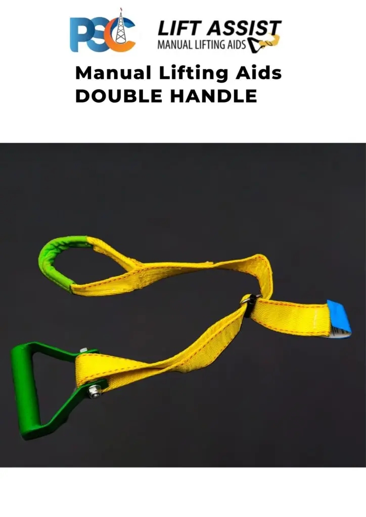
Provides an engineered grip point on components that lack one. The tool interface replaces the improvised grip on an unsuitable surface. Worker's hands are on the tool handles — in a position designed for the task.
A complementary lift interface for specific component configurations where PSC Lift Assist geometry does not match the component profile. Application review determines which tool applies.
The correct question is not "Is this component too heavy to lift?" — it is "Does the component's geometry force the worker's hands into a position that creates exposure during the lift?" If yes, a lift-assist interface may be the appropriate engineering response.
The most common error in hand-safety intervention is selecting a product before fully understanding the task. A tool is selected because it seems similar to the task, or because it was used elsewhere on site, or because it was the first one shown in a catalogue. The result is frequently a product that does not match the actual function the hand was performing — and a "trial" that fails not because the engineering principle is wrong, but because the wrong tool was chosen.
This decision tree guides you toward a tool family for an application review. It does not make a final selection — that requires confirming load geometry, weight, access and site conditions.
Before a PSC/HSF tool is trialled in any mining application, these twelve parameters should be confirmed. They determine whether the selected tool is appropriate for the specific task — and what conditions or limitations apply.
- Object / load: What is being handled, guided or held? Component identity, dimensions, weight.
- Geometry: Shape profile — flat, cylindrical, asymmetric, elongated. Does the tool interface match?
- Weight: Confirmed weight, centre of gravity, load distribution.
- Material: Ferrous, non-ferrous, coated, painted — relevant for magnetic tools.
- Movement type: Suspended, rolling, sliding, static hold, struck — determines tool family.
- Control required: Push, pull, hold, guide, retrieve, align, stabilise — maps to tool function.
- Access: Can the required stand-off distance be achieved in the actual work position?
- Stand-off required: What distance between worker and load is needed? Does the tool reach?
- Surrounding structures: Any obstructions that affect tool operation or worker position?
- Temperature / environment: Heat, moisture, contamination — affects magnetic and grip tools.
- Operator position: Where does the worker stand? Is it a safe position during tool use?
- Task frequency: How often is this task performed? High frequency amplifies the value of an effective intervention.
If all twelve parameters confirm compatibility — proceed to a controlled trial. If any parameter raises a concern, the concern must be resolved or the tool selection revisited before trial. A confirmed incompatibility is a valid result: it narrows the selection correctly and prevents a failed trial from discrediting a valid engineering approach.
● Primary application · ◐ Conditional — application review required to confirm suitability · Continued on next page
● Primary application: The tool family is the appropriate first consideration where access and geometry permit. Application review still required. ◐ Conditional application: The tool family may apply — suitability depends on ferrous material, access geometry, component configuration or other factors that must be confirmed in application review. Application review required in all cases before any tool is selected, ordered or trialled.
A tool that matches an application on paper must still be validated in the field. The conditions of an actual mine site — access geometry, load characteristics, operator familiarity, environmental factors, task pace — always differ from a generic description. The controlled trial bridges that gap.
Observe the task. Locate the hand. Name the function the hand is performing and the exposure mechanism that results. Do not proceed to product selection until this step is documented.
Choose the specific tool within the confirmed family. Confirm size, configuration and accessory requirements. Do not skip directly to trial without completing Stages 1 and 2.
Trial the selected tool on the specific task with the actual workers who perform it. The trial must be supervised, documented and assessed against the original exposure. Worker feedback during the trial is essential data — not optional commentary.
After a defined trial period, assess the result against the original exposure. Does the tool perform the required function? Has the hand's position changed? What are the operator observations and limitations? Document the outcome — whether positive or negative. A well-documented negative result is a valid outcome.
Documentation converts a single successful trial into a repeatable site standard. Without documentation, the knowledge that a particular tool works in a particular task lives only in the memory of the workers who were present. With documentation, it becomes an instruction.
A documented application study becomes the evidence base for the next intervention on the same site. It demonstrates that the methodology works, that operator feedback was collected, and that the result was assessed honestly. That evidence builds the credibility that makes the next adoption faster.
A single mine site contains the full range of applications described in this guide — and often many within the same working shift. Rigging in the crane bay, pin work in the workshop, load positioning on the truck bay, conveyor component handling in the fixed plant, cylinder movement in the store. Each is a separate exposure. Each requires its own application review.
This reference maps each tool family to its principal control function and typical mining application. Application review is required before any tool is selected or trialled on site.
From reading to application
Describe the task, the moving load and the point where hands approach the hazard. Use the PSC catalogue to identify the relevant function, then request selection support.
Browse PSC & HSF tools ↗ · Australian sources and further reading ↗